Digital technologies/3D printing/3D modeling- Intermediate/Using Parametric NURBS Software
Introduction to Fusion360
TinkerCAD is known for its simplicity, meaning it is easy to learn and use. However, its capabilities are limited. It uses a drag and drop method to create basic geometries. Theses shapes can be grouped to create more complex geometries but it takes more time to design something complex and has less flexibility. Fusion 360 is a sketch-based CAD modeling software that allows for users to completely customize their design. It allows users to design 3D objects using 2D sketches.
Fusion 360 offers 3D CAD modeling, PCB design, and 3D simulation capabilities. It is a fee-based subscription software, however, a free version is offered for personal use. The free version has some limited capabilities but most of the 3D CAD features are offered. Even with the limited features it offers more design options than TinkerCAD. To download the software, you can use your AutoCAD account and follow the link below: https://www.autodesk.ca/en/products/fusion-360/personal
Just like TinkerCAD, and with any CAD modeling software you choose to use,. Y you can export your part designs as an STL file. Using this file format, you can use any slicer of your choice to slice the design into a gcode file to print.
Fusion 360 User Interface
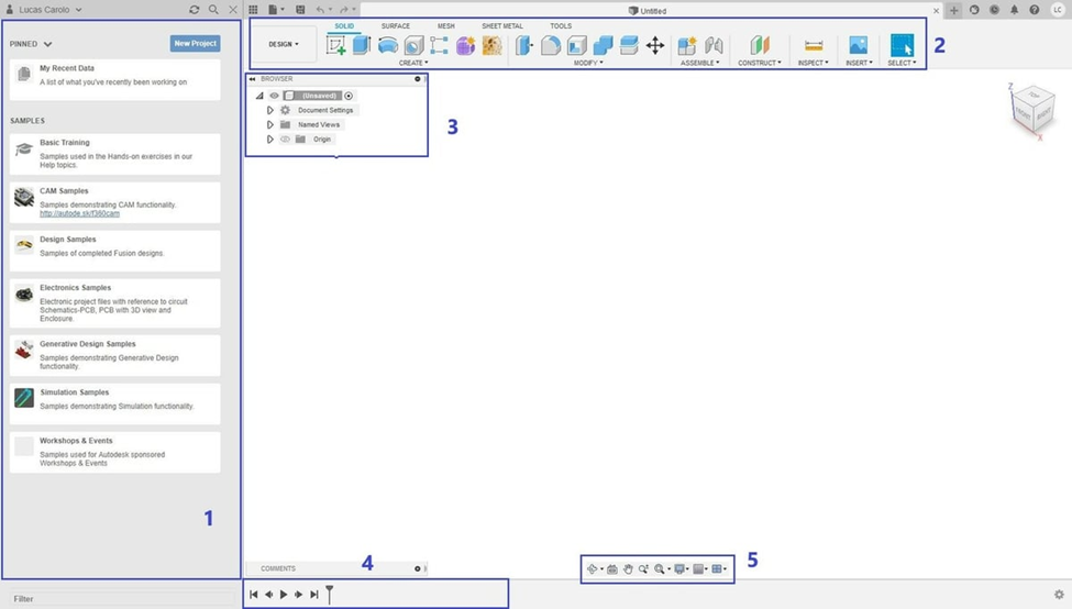
There are 5 main areas of the user interface. When the software is first launched, you should be seeing the screen above.
- Data Panel: On the left is the data panel. It displays pinned and recent projects, providing easy access to these projects for the users. It will also display sample projects that corresponds to the tutorials offered by AutoCAD. Users can also upload their projects to be shared with others for collaboration.
- Tool Bar: On the top of the screen sits the tool bar. Through this, you can use any of the features displayed to manipulate the 3D model you create. The shortcuts can be customized to display the ones you favour.
- Browser: Located at the top left of the main screen. It displays the model design with a file tree structure listing all the components, bodies and constructing plane. The files can be navigated through by clicking on their names. They can also be renamed by double clicking. The files can be collapsed using the triangles. The visibility of the bodies and planes can be toggled by clicking on the lightbulb.
- Timeline: The timeline of the design history is displayed at the bottom of the screen. This is a special feature of Fusion 360 that is different from other CAD software. It keeps a record of the construction of the 3D model allowing the users to playback the building of the model. This feature also allows users to add to the model from a previous state of the model.
- Navigation bar: The navigation bard allows users to change the view of the model. These features exist
sas shortcuts when used with a mouse. For this reason, it is recommended to create CAD models using a physical mouse instead of a track pad. Some features include:- Zoom In/Out by scrolling up/down with the mouse.
- Pan the model by holding down the wheel of the mouse.
- Orbit the model by holding down control + wheel.
Sketching
The sketch function is the most important feature of a CAD program. It allows users to sketch 2D drawings as the base to create 3D objects.
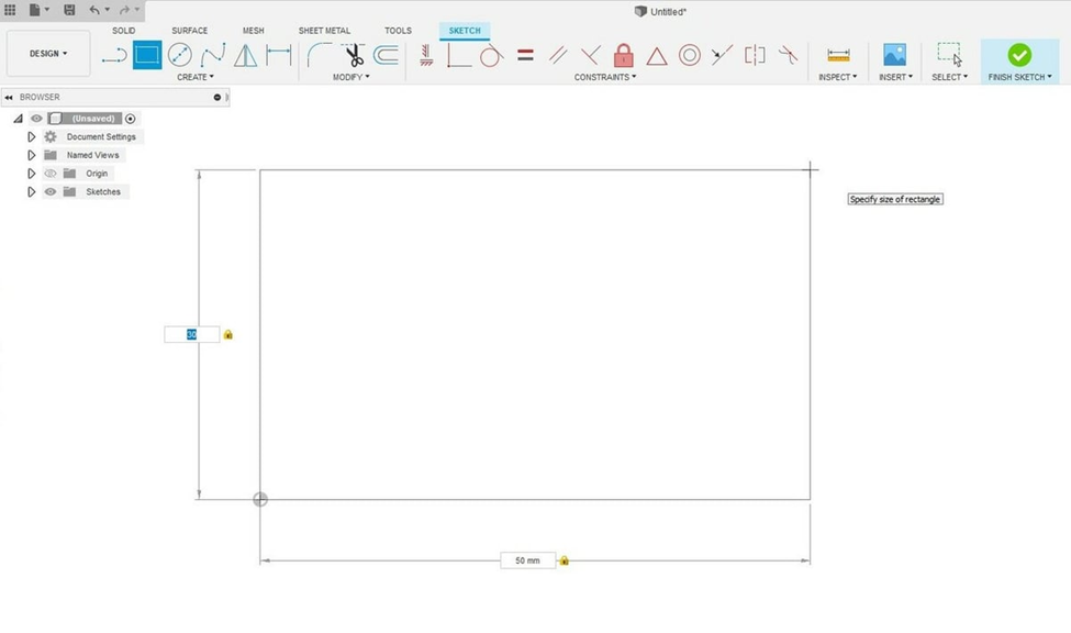
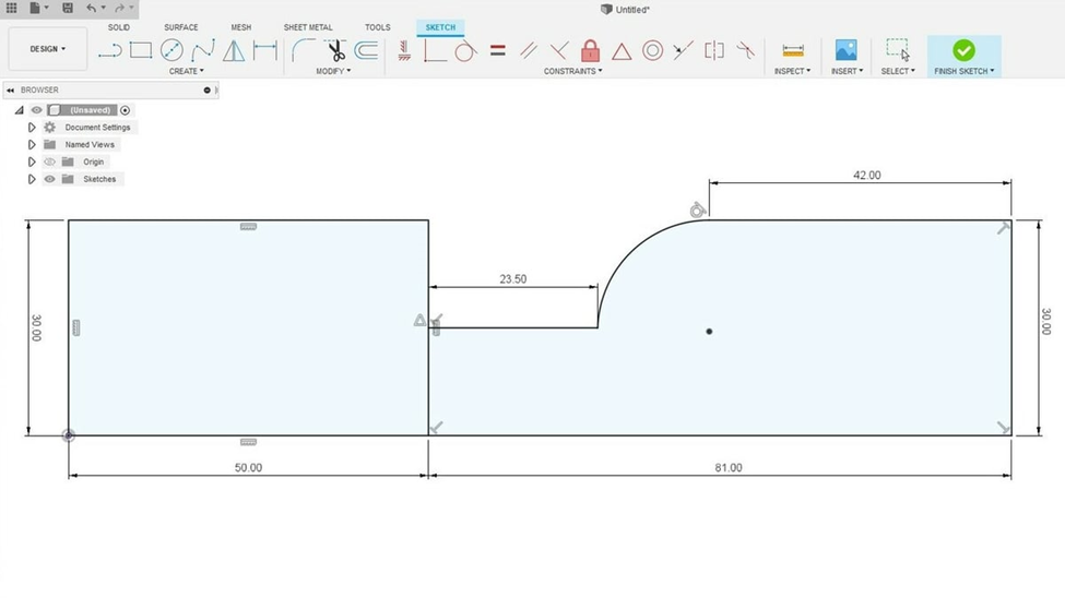
To create a rectangle, first click on “Create Sketch” from the tool bar above. Select the desired sketch plane. In the example above, YZ plane was selected. This is the plane which the 2D sketch will be created. You’ll notice the tool bar above has transformed to display sketch functions. Select “2-Point Rectangle” from the tool bar. Click on the origin of the sketch plane and drag to create a desired rectangle. The sketch features are defined with reference to the origin to position it in space. It is why it is recommended to have one vertex of the sketch to be defined as the origin. After the rectangle is drawn, you can define the dimensions of the 2 sides of the rectangle. You can toggle between the dimensions by using the “Tab” key on your keyboard. Press enter to confirm the sketch.
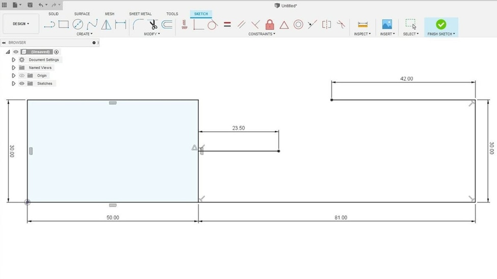
Next, the line tool will be introduced. Drawing a line is the most simple and versatile function of sketch. It will allow you to create any shapes you will need. Select the “Line” option from the tool bar. Hover your mouse over the rectangle, the mouse will be drawn to the line and an ‘X’ will appear. This means that one end of the line will intersect with the rectangle. Move the mouse towards the middle of the line on the rectangle until a triangle icon shows up. This signifies the midpoint of the line. Click to create the start of the line segment. Drag the mouse to create the line and click again to create the end of the line. You can also manipulate the dimension of the line manually by entering the value.
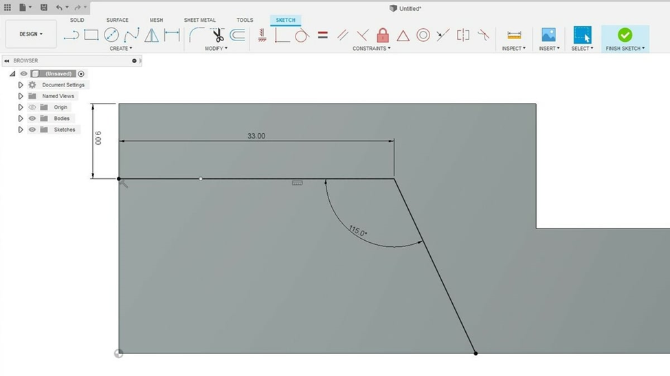
To draw the line at an angle, drag the line out at an angle. At this point, there should be an angle dimension displayed. This value can be altered manually.
To create an arc, select “Create” -> “Arc” -> “Tangent Arc” from the tool bar. This will create an arc tangent to two other entities. Left click on the vertex of where you would like the arc to connect. Then click on the other vertex to connect. Alternative to create arcs include 3-point arcs where you select the two vertex and the middle point of the arc or center point arc when the arc is created by finding the center of the arc.
In order for a 2D sketch to be converted to 3D model, the 2D profile has to be a closed shape. This means all the lines and entities have to form a closed loop. This will be indicated with a light-blue shading inside the sketch.
Extrusion
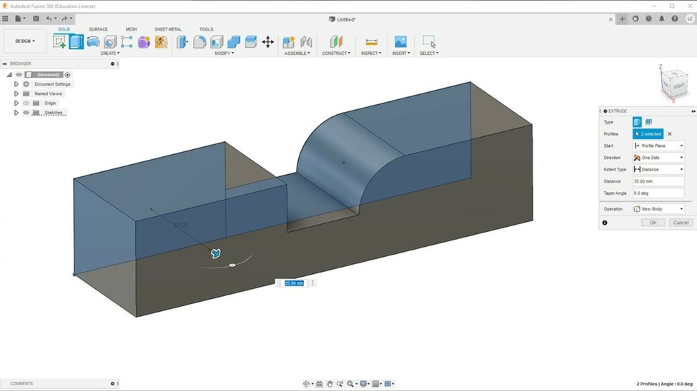
The simplest way to create a 3D model is by extruding a 2D sketch, which adds a third dimension to the 2D sketch. Select “Extrude” from the toolbar. Hover the mouse over the sketch, closed shapes that can be extruded will be highlighted when hovered on. To select multiple shapes, left click on both shapes. In the extrusion settings that pops up on the right, enter the value for the third dimension of the sketch, the width. Click “OK” to confirm the extrusion.
You can select a new surface from the extruded object to sketch on. To do so, select “Create Sketch” and select the surface you would like to sketch on as the plane. Afterwards continue to sketch like normal.
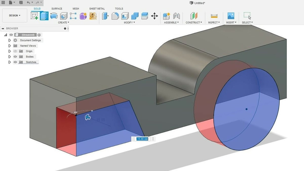
Extrusion can also be used to cut. Sketch on the surface of the shape the geometry you would like to cut. Select “Extrude” tool and select the shapes you would like to cut. To remove material, enter a negative value in the dimension window. This indicates the direction you would like the extrusion to occur. On the screen, it will display a red region to indicate material removal. Press enter to confirm the operation.
Mirror
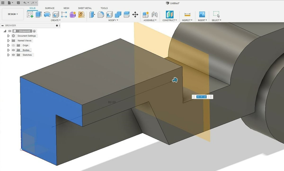
The mirror tool is an extremely powerful tool that can save the user a lot of time in creating the 3D models. This is especially useful when creating symmetrical objects. It allows users to mirror solid or small features. It does require the user to define the plane to mirror the features. There are many ways to create the plane. One of which is to “Offset Plane”
Under the “Construct” drop-down menu from the toolbar, select “Offset Plane”. Select a surface to offset from. This surface should be parallel from the plane you would like to create. Now enter the dimension you would like to offset the plane from the surface. Press enter when completed.
After the plane has been created, you can now mirror the features. Select “Mirror” under the drop- down menu from “Create” from the toolbar. Under “Type” parameter, you can select bodies, faces, features, or components. After the type has been selected, click on “Select” by Object and then the features you would like to mirror, you can also click on the features from the design history timeline. Then click on “Select” by Mirror Plane and the plane you would to mirror from. Now a preview will be displayed, to confirm press enter.
Fillet
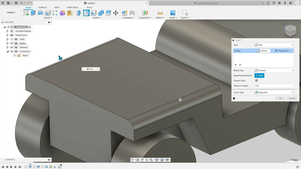
Filleting the edges is a feature that is offered in Fusion 360 and not TinkerCAD. It can easily elevate your models. It creates rounded surfaces by adding or removing from a solid model.
- Select “Fillet” under the modify menu from the tool bar.
- Click on the edges you would like to round out.
- Enter a radius value to round the edges out to.
- Click “OK” to finalize.
