Digital technologies/3D printing/3D modeling- Intermediate/Design for 3D Printing
There are some important things to note when modeling for 3D printing. It is important to optimize the print by decreasing print time and material while ensuring accuracy and strength of the part.
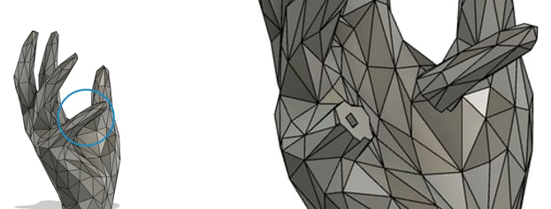
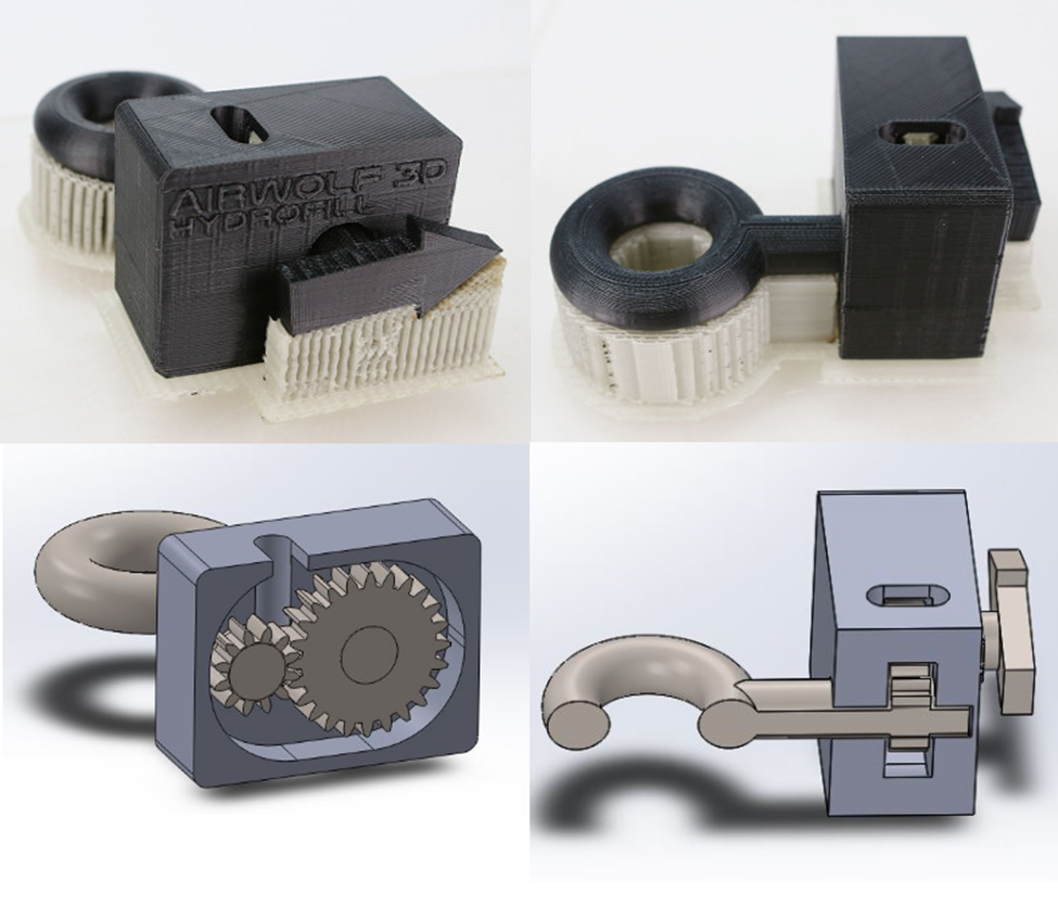
- Divide your model into smaller more manageable parts. There are many designs with complex details or large dimensions that would be more manageable prints if split into multiple parts.
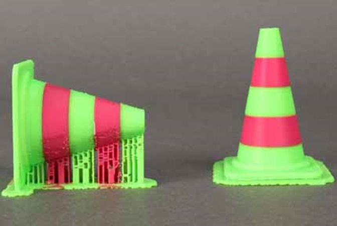
- Try to ensure that there is one flat surface on the print. This will allow easier print set-up. The flat side can adhere to the build plate, minimizing the need for additional build plate adhesion.
- Avoid floating parts. All aspect of the model should be connected to the main model. Minimize overhangs in the model as well. This will prevent wasted time and material to print supports.
- FDM printing has limited capabilities with dimensional accuracy. It is recommended to prevent printing horizontally oriented holes of the smaller size. These holes are often deformed and printed with difficult to remove supports.
- Printed parts are stronger in one direction than another. It is important to keep this in mind when designing. Prints will be weaker in the areas where the layers meet. This means that printed parts have low tensile strength along the Z-axis. The prints will be the strongest in planes parallel to the build surface.
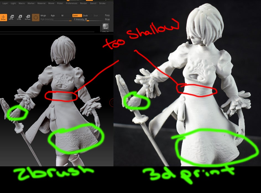
- Exaggerate the details of your designs. This is an important thing to keep in mind. In order for details to show up on small designs, you should make your cuts deeper and bigger. It can also be helpful to make slender designs thicker.
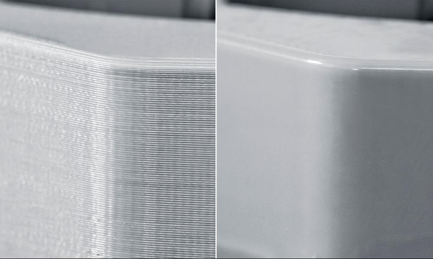
- Round surfaces will not show up smoothly. Since FDM prints in layers, it will cause the rounded surfaces to look jagged. To achieve a smooth surface, additional processing will be required.
If your design is to be used in (electro-)mechanical assemblies in which there are interfacing components, it is important that you understand three basic tolerancing concepts and to keep them in the back of your mind when modeling or more generally designing these assemblies.
- Form: The form of a part refers to the overall dimensions and the shape of the exterior surfaces of a component. Think of a flaw referring to form as a print that ended up not matching the base geometry that was used to create it in CAD due to adverse physical variables during the printing process. Examples follow:
- A sphere may end up slightly oval once printed due to improper cooling, etc.;
- A pillar might end up tilted to one side due to improper belt tension between the belt axes, etc.;
- A pin feature might end up too large to fit its mating hole due to the printer outputting too much material when producing the outer walls of the feature (the inverse can also be true).
- Position: Position refers to the distance separating a feature and an (ideally) meaningful reference (i.e.: the distance between a hole and the side of a part, or between two holes). Thankfully, flaws pertaining to position are rare on a properly tuned printer, as the printer does not have any information about existing references other than the build plate. If tuned properly, the printer will always print a feature at a position (X,Y,Z) distance relative to another feature, because that is what the gCode will tell it to do. You can imagine, however, that if the part is warped, the 'build plate reference' is no longer valid, and such, warped parts almost always have features out of position unless the meaningful reference (interfacing feature) used in the design is not the build plate. However, since the build plate reference is such an important one to define the Z position of features (for the printer, that is), making your meaningful reference something other than the build plate does not always guarantee you good positional tolerance independent of warping.
- Surface: The surface finish of a part is a rather complex subject. In 3D printing, and for typical applications of 3D printed parts, it mostly refers to the mean (statistical) difference between the height of cusps and valleys on a part and their deviation from that mean, at a macroscopic level. The most important consideration is that when 3D printing, most surface finishes are quite rough (deviate significantly from the mean), and thus are sanded down considerably to knock out the cusps left by the printer. This post processing can negatively affect the form of the final part.
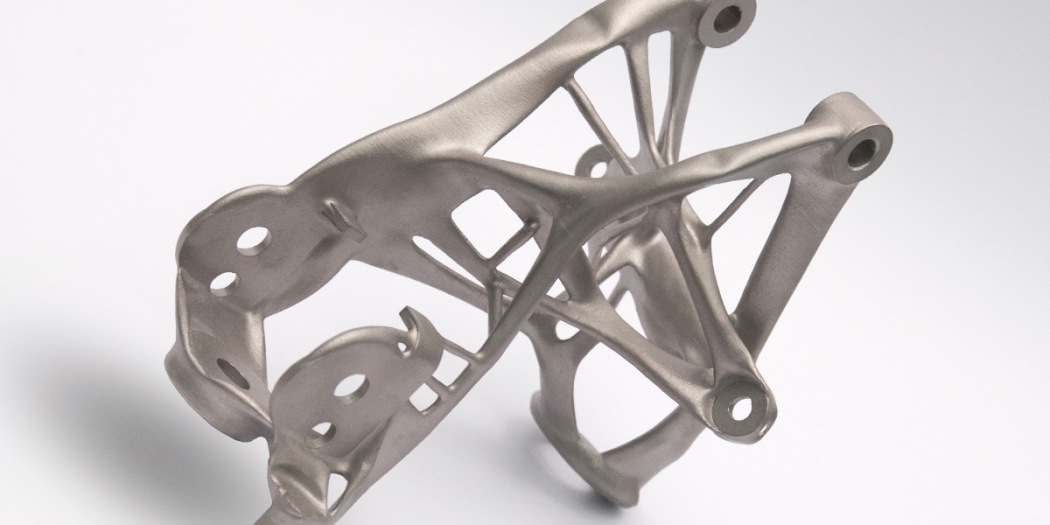
Note that a proper mechanical fit between components demands a good tolerance on form, feature position, and surface finish, such that it is typically impossible to obtain a proper fit when 3D printing, and that if you are considering the 3D printing of critically interfacing components, 3D printing should not be used unless post processing is built into the design. For mechanical designs, you will notice that a main application is brackets. This is because brackets only need good positional tolerance on holes and mating faces, which 3D printing can almost always provide (the tolerance on form for holes is not that important since they are typically clearance holes). However, since some brackets are easily laser cut, 3D printing brackets is only done under certain specific conditions. It certainly has shown its commercial use in cost cutting by replacing intricate multi-part assemblies by generatively designed (we'll say computer generated for now) parts, as shown in the picture below.
- ↑ CarrusHome (2021). GM Explores 3D printing, generative design for next gen parts. Consulted on 05-05-2022 at https://www.carrushome.com/en/gm-explores-3d-printing-generative-design-for-next-gen-parts/
